
The multibeam echosounder (fig. 20) and sidescan-sonar (fig. 21) data collected from Great Round Shoal Channel can be displayed as grids and images of the sea floor which provide detailed information on benthic character and, when combined with the subbottom seismic-profile and verification data, can be used to interpret the surficial geology.
Multibeam Bathymetry
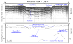
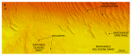
Surveyed depths within the study area range from less than 4 m to almost 50 m (fig. 20). The shallowest areas occur along the northern edge of the study area atop Great Round Shoal. Most of the study area west of the tip of Great Round Shoal is less than 20 m deep; most of the sea floor south and east of the tip of Great Round Shoal is greater than 20 m deep. Much of the benthic complexity in the western part of the study area consists of the alternating narrow elongate bathymetric highs and lows revealing the crests and troughs of adjacent sand waves (figs. 22 and 23). Crests of the sand waves are primarily oriented perpendicular to sub-perpendicular to the axis of the channel; amplitudes of the larger of these bedforms average about 5 m, but in places exceed 14 m.
Patches within the channel are characterized by isolated ridges, a hummocky appearance, and individual, rounded, bathymetric highs (fig. 23). These features, which together give the sea floor in the patches a rough topography, are interpreted to reveal lag deposits remaining from the winnowed sediments of exposed glacial drift (fig. 2). The individual, rounded, bathymetric highs are boulders, the largest of which exceeds 13 m in diameter. Isolated depressions, presumably formed and maintained by intense tidal scour, surround the southeastern tip of Great Round Shoal (fig. 24). One of these scour depressions, a northeastward-broadening elongate feature that lies along the eastern side of the shoal's tip, is the deepest spot in the study area, exceeding 49 m in depth.
Sidescan-Sonar Backscatter
Distinctive tonal patterns revealed on the sidescan-sonar mosaic (fig. 21) include: (1) individual high-backscatter targets (objects), (2) areas of relatively high backscatter (light tones), (3) areas of relatively low backscatter (dark tones), and (4) alternating bands of high and low backscatter in a "tiger-stripe" pattern. Boundaries between patterns are commonly gradational; backscatter is not uniform throughout these areas.
The individual high-backscatter targets, which also concentrated into areas forming complex patches of high and low backscatter, delineate the rocky, bouldery areas of the exposed glacial drift (fig. 25). Rocky areas are concentrated within the areas characterized by relatively high backscatter. The higher backscatter tends to be produced by coarser-grained sediments, typically gravel and gravelly sand. Narrow, elongate patches characterized by relatively low backscatter (fig. 26) are also commonly scattered within the areas of high backscatter. These patches of low backscatter trend northeast, are produced by finer grained Holocene sand, and give the sea floor a current-swept appearance.
Areas characterized by alternating bands of high and low backscatter include most of the western, north-central, and eastern-most parts of the sidescan-sonar mosaic. This "tiger-stripe" pattern (figs. 26 and 27), which is produced by sand waves and megaripples, results from a combination of topographic changes affecting the angle of incidence of the sidescan sonar and the differences in sediment texture commonly present between crests and troughs of the bedforms (Reineck and Singh, 1980).
|
Click on figures for larger images.
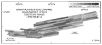
 | Figure 2. Segment of high-resolution seismic-reflection Uniboom profile (O'Hara and Oldale, 1987) and interpretation of ASTERIAS 77024 line 35. Location of seismic profile shown in figure 22.
|
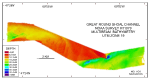 |
Figure 20. Digital terrain model (DTM) of the sea floor produced from multibeam bathymetry collected during NOAA survey H11079 of Great Round Shoal Channel, offshore Massachusetts. Image is sun-illuminated from the north and vertically exaggerated 5x.
|
 |
| Figure 21. Map showing the sidescan-sonar imagery produced from data collected during NOAA survey H11079 of Great Round Shoal Channel, offshore Massachusetts. Light tones are hard returns and generally coarser grained sediments; dark tones are softer returns and generally finer grained sediments. Tonal artifacts caused by inaccurate across-track normalization during processing complicate interpretation of the sidescan-sonar imagery.
|
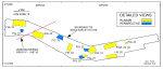 | | Figure 22. Map showing the boundary of the acoustic data from NOAA survey H11079 of Great Round Shoal Channel and the locations of the detailed planar, perspective, and comparative views of the multibeam DTM and sidescan-sonar mosaic shown in other figures, and the seismic profile shown in figure 2. |
 | | Figure 23. Detailed planar view of exposed glacial drift and the sand waves at the transition from shoal to channel from the DTM produced during NOAA survey H11079. Note that crest-line bifurcations are most common along the edge of a sand-wave field and that boulders are present on the exposed surface of the glacial drift. Location of view is shown in figure 22; depth key is shown in figure 20. |
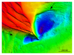 | | Figure 24. Detailed planar view of scour depressions flanking the southeastern tip of Great Round Shoal from the DTM produced during NOAA survey H11079. Note that the scour depression northeast of the tip is deeper and larger. Location of view is shown in figure 22; depth key is shown in figure 20. |
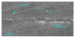 | | Figure 25. Detailed planar view of a comet structure associated with a boulder from the sidescan-sonar mosaic produced during NOAA survey H11079. Higher backscatter within this feature shows that coarser grained sediment is present there; scour asymmetry indicates that net transport is to the northeast. Location of view is shown in figure 22. |
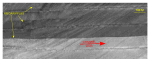 | | Figure 26. Detailed planar view of the sidescan-sonar mosaic produced during NOAA survey H11079 showing the current-swept appearance that characterizes much of the eastern part of the study area. Note the isolated patches of megaripples. Location of view is shown in figure 22. |
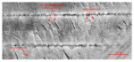 | | Figure 27. Detailed planar view of the sidescan-sonar mosaic produced during NOAA survey H11079 showing relatively straight to sinuous alternating bands of high and low backscatter ("tiger-stripe") pattern indicative of transverse sand waves. Note presence of megaripples on the stoss slopes indicative of active transport. Location of view is shown in figure 22. |
|


