Woods Hole Science Center
U.S. Geological Survey Open-File Report 2005-1048
Geological Interpretation of Bathymetric and Backscatter Imagery of the Sea Floor Off Eastern Cape Cod, Massachusetts
METHODS
|
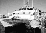
The acoustic data presented herein were collected offshore of Cape Cod, Massachusetts, with a multibeam sea floor mapping system during USGS cruise 98015, conducted November 9 - 25, 1998. The survey, covering approximately 153 km2 of the sea floor, was conducted using a Simrad EM 1000 multibeam echo sounder hull-mounted aboard the Canadian Coast Guard vessel FREDERICK G. CREED, a SWATH (Small Waterplane Area Twin Hull vessel; Figure 6). This multibeam system utilizes 60 electronically aimed beams spaced at intervals of 2.5 degrees that insonify a strip of sea floor up to 7.5 times the water depth (swath width of 100 to 200 m within the survey area). The horizontal resolution of the beam on the sea floor is approximately 10 percent of the water depth. Vertical resolution is approximately 1 percent of the water depth. Datasets derived from the mulitbeam observations show sea floor topography, shaded relief, and backscatter intensity (a measure of sea floor texture and roughness) at a spatial resolution of 4 m/pixel. Together these datasets cover an elongate, narrow band of the sea floor extending from Provincetown to off Monomoy Island. Width of the sea floor covered by the datasets ranges from less than 600 m to over 2100 m, a variation resulting from changes in the number of ship tracks along which the multibeam data were collected. Although typically of continuous coverage, small patches of no data in the datasets (notably northwest of Provincetown) result from divergent ship tracks. Data acquisition and most of the processing were performed at sea. After the echo sounder data were logged onto a Sun workstation hard drive, a suite of processing software developed by the Ocean Mapping Group was used to correct for artifacts and errors that may have been introduced during data collection. This software also enhanced the corrected data by resolving beam pattern and aspect ratio distortions and by imposing a linear contrast stretch before it generated bathymetric and sidescan sonar image mosaics in a Mercator projection. All data processing described here is initiated using Silicon Graphics workstations as soon as each acquisition file is closed by the Simrad Mermaid workstation (usually at the end of each survey line). The processing and editing steps preformed on the acoustic data on board the ship included:
The processing and editing steps completed post-cruise on the acoustic data in the lab included:
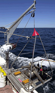
To verify the acoustic data, surficial sediments (0-2 cm below the sediment-water interface) and (or) bottom photography were collected at 89 stations during May-June 2004 aboard the research vessel RAFAEL (Figure 7). The samples and photography were collected with a modified Van Veen grab sampler equipped with still- and video-camera systems (Figure 8). The photographic data were used to appraise intra-station bottom variability, faunal communities, and sedimentary structures (indicative of geological and biological processes) and to observe boulder fields where samples could not be collected. Pre-existent surficial sediment data (Poppe and others, 2003) were also used to supplement the newer sediment data.
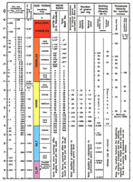
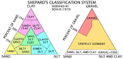
In the laboratory, the sediment samples were disaggregated and wet sieved to separate the coarse and fine fractions. The fine fraction (less than 62 microns) was analyzed by Coulter Counter; the coarse fraction was analyzed by sieving; and the data were corrected for salt content. Sediment descriptions are based on the nomenclature proposed by Wentworth (1922; Figure 9), the inclusive graphics statistical method of Folk (1974) and the size classifications proposed by Shepard (1954; Figure 10). A detailed discussion of the laboratory methods employed is given in Poppe and Polloni (2000). Because biogenic carbonate shells commonly form in situ, they usually are not considered to be sedimentologically representative of the depositional environment. Therefore, gravel-sized bivalve shells and other biogenic carbonate debris were ignored.
To facilitate interpretations of the distributions of surficial sediment and sedimentary environments, these data were supplemented by sediment data from earlier studies and compilations in Cape Cod Bay, Massachusetts Bay, and the Gulf of Maine (Poppe and others, 2003). These other sources include Hathaway (1971), Schlee (1973), Schlee and others (1973), Stetson (1938), Poppe and Polloni (2000), and unpublished datasets from the National Geophysical Data Center. The interpretations of sea-floor features, surficial sediment distributions, and sedimentary environments presented herein are based on data from the sediment sampling and bottom photography stations, on tonal changes in backscatter on the imagery, and on the bathymetry. Because of the geographic extent of the dataset and to limit file size, the imagery and interpretive data layers have been divided into northern and southern halves. This division roughly coincides with the boundary between the Towns of Truro and Wellfleet. |